
Nozzle Design
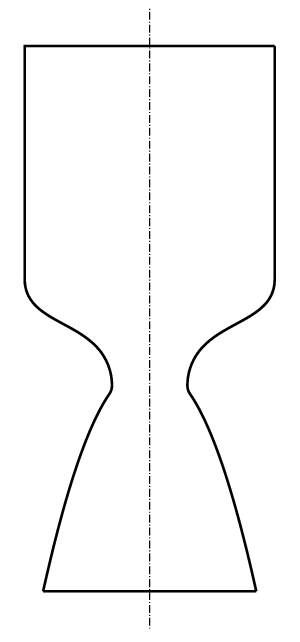
chamber, throat, and nozzle.
After combustion, the high temperature and pressure gas escapes through the nozzle. The role of the nozzle is to increase the velocity of the gas by reducing its pressure.
The exhaust flows towards the throat, which is sized to choke the flow, accelerating it to the speed of sound. Beyond the throat, the nozzle expands until the flow is travelling several times the speed of sound.
Due to the fixed shape of the nozzle, the velocity (and therefore pressure) at the exit is fixed. This presents a problem during flight. As the rocket travels toward space, the ambient pressure decreases exponentially. A nozzle is optimal when the exit pressure is the same as the ambient pressure; a pressure difference is suboptimal. The chosen exit pressure is called the design condition, and can be referred to as the design altitude—the altitude corresponding to the chosen exit pressure.
Typically, design altitudes greater than sea level are used on the first stage of launch vehicles, because immediately after launch the ambient pressure starts getting lower, exponentially so as shown in figure 2.
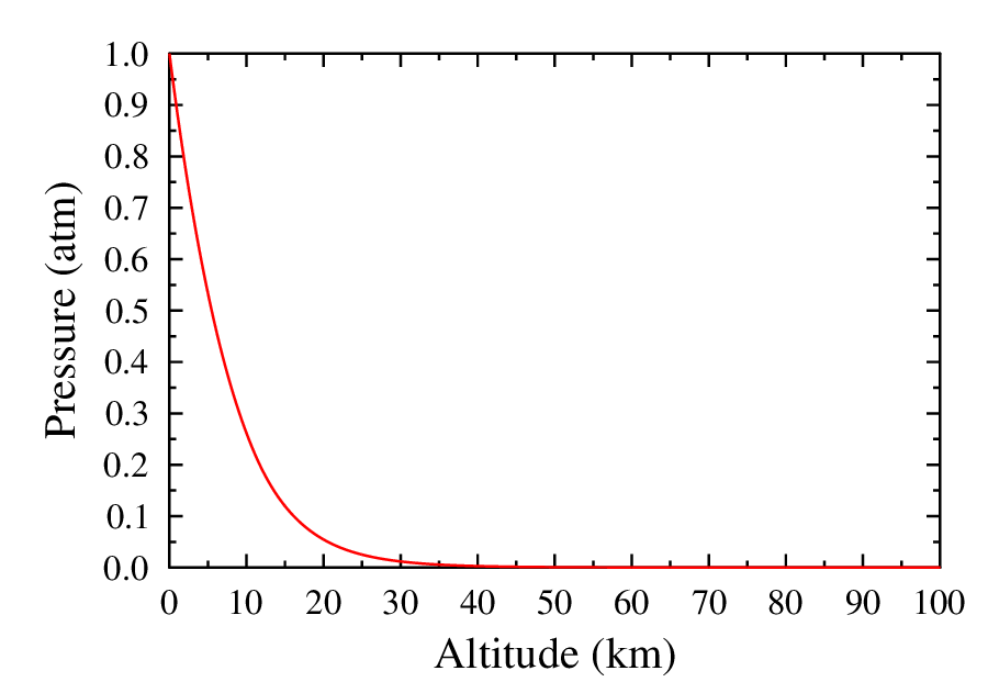
The first stage of orbital launch vehicles can operate up to 100 km, which is a relative vacuum compared to sea level. [Please note that the linear $y$-axis doesn’t truly reflect the exponentially decreasing pressure.] There is a limitation however; the exit pressure at launch cannot be less than 0.25 to 0.4 atm, or the flow will separate from the nozzle wall and prevent full thrust.
Although typical launchers can be designed as mentioned, our engine has very different requirements. It is also of note that to reach 100 km, the engine will only need to fire up to about 40 km. The main difference in the requirements for our engine is the ability to land.
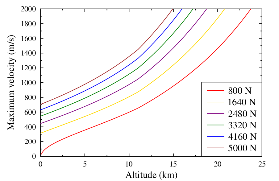
During descent and landing, the nozzle is directly facing the flow. It was found that the stagnation pressure significantly increased the total pressure. Due to the flow separation limits previously mentioned, a design altitude of sea level was chosen. Figure 3 shows the maximum velocities that can be achieved for this design condition. It is strikingly clear that the 800 N thrust requirement would not be met for a higher exit pressure.